My girlfriend told me over the weekend that she would never have her hair done by a hair stylist with ugly hair. That's the same reason why, tuning shops need to have a nice demo car and why if you sell furniture for a living you need to have the nice stuff at your own house too. You can't be credible if you don't walk the talk.
The reason I bring this up is that with the advent of all of these forums and even more recently facebook based car clubs it's a bit surprising how much misinformation is out there. It's fine of course if like me, you take everything you read online with a grain of salt. You find some new information, verify where it came from, do a little more research into it and learn. Sometimes it can be a ruse to send you off on a wild goose chase, like when I started looking into information I got about how to upgrade the Lancer's front disc brakes. Misleading- yes, yet while chasing around the proverbial goose we did learn new things and find our own way.
There are however people out there who are, as politically correct as I can put it, more trusting. They get advice and go with it, sometimes not bothering to check where it came from. That's alright if what they were told do do is right in the first place. But sometimes there are quite a bit of people out there who might seem to know a lot when they are posting about this and that, yet in truth they are just really adept at using Google or quite good at retelling stories they have heard from others.
Reading through discussions there are a few terms that pop up quite often. One that I always here is that a certain part or some bit of information car from this so and so who used to race. The big names that we all know aside of course, the funny thing is that quite often people don't ask.. 'yes he used to race... but did he win?' Case in point, a friend of mine bought a cylinder head for his Lancer for a certain someone who used to race. Big valves, double valve springs and heavily ported and polished it was said to be 'too wild to use on the street'. Sounds exciting right? However when we inspected it, the valve springs were not set in the proper retainers, the big valve conversion was so-so and the porting was so bad, I we figured that head would actually give less power than a stock one. Another things I always here is that the work was done by this guy who used to have a car shop. This is even scarier. Why used to? If he was good or even at least decent he'd still have one today (there are exceptions I know) but we've had work done on one of our cars from such a guy and I spent a good amount of time re-tightening all the bolts because after a little bit of driving things started to come loose (among quite a bit of other mess I had to fix after). The transmission bolts were barely hand tight.
So now you know, before you have your hair done, check to see if the stylist looks good.
Edit: I realized while re reading the article. How strange is it that not only do I do I work on my own car... I also style (well, shave is more accurate) my own hair. :P
Friday, March 2, 2012
Friday, February 24, 2012
Win a Tsurikawa contest!!
In my previous blog post about why you need a thermostat I intentionally made a mistake. I'll give a genuine Japanese Bosozoku 'stolen-from-a-bus' Tsurikawa to the first person who can comment and point out what that mistake is. Hint; it's in the pictures. Don't worry there's nothing wrong in the information I provided. :)
Edit: and the answer is... I posted the pics that had the thermostat installed in the car the other way around.
This is wrong;


Edit: and the answer is... I posted the pics that had the thermostat installed in the car the other way around.
This is wrong;


This is the right way to install it;


The orientation of the thermostat is important. The wax end of the thermostat has to be facing the inside of the engine and the other side towards the radiator. This makes sure that when the water in the engine is hot the thermostat will open to let the cold water for the radiator in. Get that reversed and the thermostat will not open until the water coming in from the radiator is at the thermostat's pre set temp, so it will be already hot when it goes into the engine.
The original article has also been updated.
Congratulations to Mr. Jerry Baniqued for winning the Tsurikawa. :P
Thermostat: why you need it
I have been meaning to do the write up for this, among other things I have wanted to write about, for a while now. So let's get started in this. To be honest, this topic is new territory for me having only learned this whild trying to sort out a cooling system problem in our Turbo Diesel Hyundai Starex. I'm an now applying knowledge learned to my '79 Lancer project car. Previously I did not believe in using a thermostat in a hot tropical country like the Philippines. There are many arguments against it. It is commonly believed that the thermostat is only used to keep the engine hot in cold countries, something we don't need here. We normally thing that it's best to keep the water temp as low as possible. Bottom of the temp gauge is best to keep the engine as cool as possible. Thermostats also have the tendency to get stuck up as they get old, more often than not they get stuck in the closed position leading to overheating problems.


P.S. always use coolant with your water, and always used distilled water because both of those prevent the engine from rusting on the inside and prevent it from having mineral deposits. This also prolongs the life of the water pump. Upgrading to a higher pressure radiator cap (1.2 or 1.4 Bar vs the stock 0.9) is also a good idea for a high performance engine. High pressure makes the water harder to boil. A radiator cap from W123 Mercedes Benz will be a nice upgrade for your old-school Japanese car since this is a high pressure cap and it's only a fraction of the price of performance rad caps from Ralliart, TRD or Spoon, not that those come in sizes for old-school cars anyway.
Credit to my friends from SMT Competion Headers for showing me the right way. Otherwise I would still be ignorant to the importance of this. :)
To start with, let's have a little looks into how a thermostat works and how it relates to the cooling system as a whole.
This is a thermostat, the cooling system thermostat of course not to be confuse with the A/C switch that control temperature that is also called a thermostat...

The thermostat comes in all sorts of shapes and sizes but more or less they look the same. The cylinder at the bottom contains a calibrated amount of wax designed so that when it is exposed to hot water, the was will expand and open the thermostat at its set temperature. Usually more or less 90 deg. Celsius. The one I got for my car is 86 deg. The spring will close the thermostat as the wax contracts when it's exposed to cool water.
The UFO shape let's in fit into a housing somewhere in the car's cooling system. This is usually a round area where the upper radiator hose goes into the engine although I have seen it also at the entrance of the water pump in some engines.
The orientation of the thermostat is important. The wax end of the thermostat has to be facing the inside of the engine and the other side towards the radiator. This makes sure that when the water in the engine is hot the thermostat will open to let the cold water for the radiator in. Get that reversed and the thermostat will not open until the water coming in from the radiator is at the thermostat's pre set temp, so it will be already hot when it goes into the engine.
The common belief is that all this thing does is make sure the engine is at operating temperature be staying closed as the engine is still cold then opening. But actually it does a lot more than that. It is never always open once the engine is at operating temperature. It opens and closes at needed to control the flow of water in and out of the engine and radiator.
With out the thermostat the water freely circulates, the water pump pulls cooled water from the radiator then pushes this through the water channels in the engine block into the cylinder head where the water absorbs heat and then is pumped back into the radiator. The higher the engine speed (RPM) the faster this happens. Unless you have a really huge radiator, the problem is that at really high engine speeds the water is moving so fast that it does not spend enough time in the radiator to be able to cool enough. This is the reason why the water temperature goes up when running prolonged high speed if the car is not equipped with a thermostat- do that long enough and that could lead to overheating.
With a thermostat installed, the water in the system gets halved. Half stays in the engine to cool it, the other half stays in the radiator to get cooled. When the water in the engine gets hot enough it will open the thermostat causing the cool water from the radiator to flow into the engine and the hot water in the engine will flow to the radiator. The cool water in the engine will then make the thermostat close allowing the water inside the engine to absorb heat and keeping the hot water in the radiator, which of course is a heat exchanger, allowing it more time to dissipate it's heat before going back into the engine. This exchange happens at the calibrated temperature of the thermostat, so even at prolonged high engine speed the water will always have time to stay in the radiator and the temperature will stay constant all the time.
Constant temperature. The thermostat will maintain water temp at more or less half of the temp gauge. In the past I had always thought that it is best to have the water temp as low as possible. That's why my car was equipped with a huge 3 row radiator, high pressure cap and a huge electric cooling fan plus a second auxiliary fan. It was only when I started to delve into the finer points of engine tuning that I realized how wrong that setup was.
There are a lot of variable that affect engine tuning. Some of them we cannot control, like outside air temperature and air density changes due to changes in elevation (when driving up a mountain) so it is best to control and keep constant the variables that we can control in order to keep our tune more constant. Be keeping water temperature constant and at just the right heat, the thermal expansion of the metal in the engine will be constant. this is an important consideration when breaking in a newly rebuilt engine as this gives the piston rings and bearings the opportunity to expand to their ideal running clearances and most importantly stay there.This will also mean that the temperature in the combustion chamber will be constant so our mixture setting for the carbs will not have to be varied as much since the engine will always be at the same optimum engine temperature for the settings.
One fear I had when setting up the twin side drafts carbs for my car were the old stories that cars equipped with twin side carbs would struggle to get up Kennon road going to Baguio City without having the change their mixture setting (or in some stories even the jettings) to something much leaner about 3/4 the way up the mountain. I later learned from more credible sources that the reason for this was not only because of the altitude change, but rather because most of those engines were no longer equipped with thermostats they would have likely been running cold, giving less than ideal conditions for fuel atomization and combustion. A properly tuned car with twin side drafts and an engine at the ideal temperature should have no problems making the climb.
The only disadvantage to running a thermostat is that it could get stuck closed when it ages. This though is nothing that good old fashioned preventive maintenance can't take care of. Thermostat units are pretty inexpensive so it won't hurt to change it to a new one every two or three years. It is also a good idea to learn how to monitor your gauges. The thermostat will maintain temperature at around half, that is quite a long way from 3/4 of the gauge and even longer to the point of the gauge that's red where the engine is overheating. So even if you did forget to change the thermostat before it got stuck up there's no reason for you not to notice that the temperature is higher than normal and pull over before the water completely boils over.
Some pics!
This is where the thermostat usually lives. A round housing where the upper radiator hose meets the engine;

Inside, there is usually a groove where the thermostat sits in.

This is what the water coming from the radiator 'sees' :P

And lastly, if you are reading this blog, chances are you own a Mitsubishi 4G32/33 engine. If I have convinced you of the merits of running a thermostat and you wish to install one, you will find that it is rather hard to find an original one for a 4G3x (at least in the places I looked it was). You will be happy to know though that a thermostat for a Mazda 323 will work just fine. That's what I used. Here's the box with the part numbers;

Credit to my friends from SMT Competion Headers for showing me the right way. Otherwise I would still be ignorant to the importance of this. :)
Friday, February 17, 2012
Attention to detail
I often get asked why it's taking so long to finish my project. So, I decided to show a little something that will give a little insight into my little world.
Aside from the obvious boring reality that I have a job that also demands my time and a personal life to attend to, what eats up the time working on the car is the attention to detail we have to put into it. It's easy to slap things together and call it a day, but the small details are what sets us apart from the posers. Here's a little example...
Today I was working on changing the studs on the intake manifold to longer ones to accommodate the carbs, Phenolic spacer and the throttle cable bracket. The studs I got were longer, but then too long so they had to be trimmed to clear other parts of the carbs. Most people would just cut them and go on... But look what I'd do...

From left to right; the stock stud, cut down to size with a hack saw and then finished on a grinding stone to smooth the top and round it off to a similar profile as the original. I then clean the finished product up so it looks like new before installing it.
Repeat that process 8 times for all the intake manifold studs and you'll see where the time is spent. Every part of the car is treated with the same attention to detail. Most of these things, really are not even seen when the car is finished but I do derive some sort of personal satisfaction knowing it's there.
Today I was mocking up the positioning of the A/C condenser and oil cooler for the car;


While doing this I got to look inside the bits of the car that are usually hidden from view. This is how it looks without any cleaning or anything. 3 years on since I restored the car (and it has been used quite a bit since then) I'm pretty happy with how it looks in there. All the accessory brackets are powdercoated, new bolts were used in the assembly and the backs of the fenders and wheel wells were coated with a Wurth resin based undercoating before everything was sprayed inside out with Anzhal car show finish urethane paint. All of that detailing is what takes time, but, at least in my opinion it's worth all the effort.
Wednesday, February 1, 2012
Power to Weight Ratio demo.
Saw this posted by a friend over at our forum 1stgenlancer.co.nr.


(it's an animated GIF. click image to play it!!)
It's not power that matters... It's power to weight!!
Saturday, January 21, 2012
How to set valve clearances
This is something that I've been asked about a lot in the forums but I've always been a little too lazy to make a step by step guide on how to do it. But since I had my engine out and on the stand and everything is easy and accessible I decided to get some shots and make a quick write up on how to do this yourself.
It's pretty easy to do with just some basic tools and a little time and effort, yet I have even read that there are some so called mechanics out there who do not know how to do this (change your mechanic!) or worse claim to know but set it all wrong.
So, here goes...
Valve clearance setting only applies to engines that use solid lifters. If the engine uses a hydraulic lifters the procedure is very different (although easier!) it's something I can teach show some other time.
After the obvious like shutting off the engine and removing the necessary parts to get access to the rocker arms. The first step to setting the valve clearances properly is to understand the concept of Top Dead Center (TDC) sometimes called the Zero Setting by others. This is also useful in setting other timing related components of the engine like the ignition, timing belt and the distributor. at TDC the #1 piston will be at the very top of it's compression stroke. That is at the point where it has finished travelling upward, compressing the air/fuel mixture and will begin travelling downward. There are 3 indicators that the engine is at this position. These will vary slightly from engine to engine but more or less all engine have some marking to identify these.
 The notch of the crank pulley, painted in white to enhance contrast against the black pulley. will align with the 'T' mark on the timing cover. This T is sometimes 0 (zero) in other engines.
 A mark on the cam gear (a dot in this case) will align to a mark on top of the case. This is important because the crank pulley will pass thru it's top dead center mark twice before the cam gear aligns to its mark at TDC. This is because the camshaft is driven a 50% of the crank shaft speed. So just because the crank pulley is aligned at T, it does not mean the engine will be at TDC.
 The valves of the #4 cylinder will be 'on the rock'. This means that the lobe of the the intake valve will be just about to close the valve while the exhaust will be just about to open. You may need a sharp eye to spot this, it's very obvious here with my 4G33 because the Rally Cam has a lot of valve over lap so the time the intake and exhaust are open together is longer and thus its being on the rock is easy to spot.
 Rotate the engine in it's normal direction of rotation (avoid going backwards as much as possible) until it is set to top dead center. This is usually clockwise save for a few (like Honda engines) that rotate anti-clockwise. In a FWD car with a transverse engine there will be a slot on the side of the wheel well where you can stick a socket wrench through to rotate the engine.

Before we begin setting the valves it is important to be familiar with the 'on the rock' position and the pistons running mates. TDC is easy to find because it has it's markings and will let us set the valves of the #1 piston. But the other pistons being at top dead center will rely on being able to spot if its running mate is on the rock. In almost all 4 cylinder engines #1 and #4 run together while #3 and #2 run together. That is they will be both at the top or bottom of their stroke together.
 Now we can start setting the valve clearances. It is important to use a good quality set of feeler gauges for this. I set my engines to 0.007 inches for the intake and 0.011 inches for the exhaust. For performance tuning we can have a long discussion about what clearances to run, but for now I would suggest to use whatever the factory spec is for your car. Note also that this is a cold setting. The valve clearances for a hot engine will be looser due to thermal expansion although I don't know why you would want to work on a hot engine.
 With the engine set to TDC the valves of the #1 cylinder can be adjusted. Loosen the nut on top of the rocker arm...
 ... and use a flat screw driver to turn the adjustment screw in or out until the desired valve clearance is achieved. This should be set where the feeler gauge can just barely slide in and out from between the rocker arm (that's why my gauges have a bit of scratches on my favorite settings). Holding the adjustment screw steady with the screw driver, re-tighten the nut and then double check that the clearance has not changed. Do this for intake and exhaust of the #1 cylinder.
 With the valves of #1 adjusted it will be time to adjust the next cylinder in the firing order. It's 1-3-4-2 for most 4 cylinder engines (check yours to be sure!) so #3 gets adjusted next. The running mate of #3 is #2, so watch for the valves of the #2 cylinder to be on the rock. After adjusting #3, rotate the engine again to adjust #4. In this position it's running mate, #1 will be on the rock. The finally rotate the engine again to adjust #2, watch for when it's partner #3 is on the rock. The you're done.
If that last paragraph maybe a bit confusing refer to this;
It's pretty easy to do with just some basic tools and a little time and effort, yet I have even read that there are some so called mechanics out there who do not know how to do this (change your mechanic!) or worse claim to know but set it all wrong.
So, here goes...
Valve clearance setting only applies to engines that use solid lifters. If the engine uses a hydraulic lifters the procedure is very different (although easier!) it's something I can teach show some other time.
After the obvious like shutting off the engine and removing the necessary parts to get access to the rocker arms. The first step to setting the valve clearances properly is to understand the concept of Top Dead Center (TDC) sometimes called the Zero Setting by others. This is also useful in setting other timing related components of the engine like the ignition, timing belt and the distributor. at TDC the #1 piston will be at the very top of it's compression stroke. That is at the point where it has finished travelling upward, compressing the air/fuel mixture and will begin travelling downward. There are 3 indicators that the engine is at this position. These will vary slightly from engine to engine but more or less all engine have some marking to identify these.


Before we begin setting the valves it is important to be familiar with the 'on the rock' position and the pistons running mates. TDC is easy to find because it has it's markings and will let us set the valves of the #1 piston. But the other pistons being at top dead center will rely on being able to spot if its running mate is on the rock. In almost all 4 cylinder engines #1 and #4 run together while #3 and #2 run together. That is they will be both at the top or bottom of their stroke together.


If that last paragraph maybe a bit confusing refer to this;
- Adjust #1 cylinder when; Crank pulley and cam gear are at TDC, #4 cylinder is on the rock.
- Adjust #3 cylinder when #2 cylinder is on the rock.
- Adjust #4 cylinder when #1 cylinder is on the rock.
- Adjust #2 cylinder when #3 cylinder is on the rock.
Thursday, January 5, 2012
Champion CT-410 Gapping Tool
First post of the new year! And let's start by taking a look at a nifty little vintage tool I have.
It's a Spark Plug Gapping tool made by Champion (spark plug company). The model code says CT-410. I tried to do a web search and the only info I can find is that it's old. I inherited this tool from my Dad who says it was given to him by someone in the 80's.
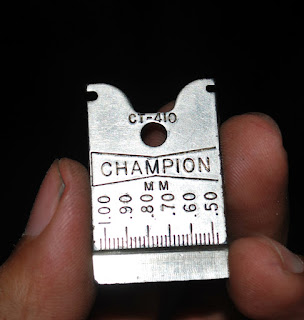 The front part of the tool has the measurements in millimeters from 1.0mm to 0.50mm. The reverse side displays the equivalent in inches and would be useful if you're working on an american car that lists specifications in Inches. Apologies for lack of pic of that side, I forgot to snap the pic and the tool is back in the shop as of this writing.
 The side profile shows the wedge.
 To Gap a Spark Plug simply slide it across from the skinny side of the wedge to the fat side until the tip lines up with the specified gap setting. This is also useful for checking to see how much the gap of used plugs have 'opened up' before resetting the gap.
 The top end of the tool has a little hook thing that fits into the electrode that will allow for it to be pushed down to close down a gap that has opened up too big.
It's interesting how simple the concept of this tool is yet I have not seen this really catch on. To date I don't know of anyone else who has one. I'd like to hear from you if you do or if you have something similar. I don't really get to use this much since I started using Iridium Spark Plugs in my engines, as those come pre-gapped and the Iridium is so hard it's impossible to re-gap them without breaking the tip off (Yes, I've tried). But it is an indispensable tool when working with ordinary copper plugs.
It's a Spark Plug Gapping tool made by Champion (spark plug company). The model code says CT-410. I tried to do a web search and the only info I can find is that it's old. I inherited this tool from my Dad who says it was given to him by someone in the 80's.


It's interesting how simple the concept of this tool is yet I have not seen this really catch on. To date I don't know of anyone else who has one. I'd like to hear from you if you do or if you have something similar. I don't really get to use this much since I started using Iridium Spark Plugs in my engines, as those come pre-gapped and the Iridium is so hard it's impossible to re-gap them without breaking the tip off (Yes, I've tried). But it is an indispensable tool when working with ordinary copper plugs.
Subscribe to:
Posts (Atom)